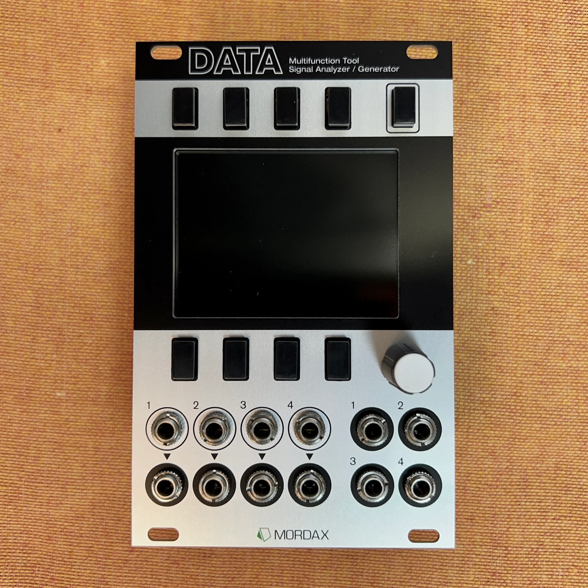
This is EP.3 of our Mordax DATA guide series. EP.1 and EP.2 covered the programs that measure and visualize voltage. This time, we'll look at DATA's signal-generating side — the Waveform Generator, Clock Output, and Voltage Monitor programs.
DATA is a measurement tool, but it also works as a source that puts out oscillators, clocks, and CV/Gate. With these programs, a single module handles both generating signals and monitoring them.
Takazudo Modular publishes manuals and related documents with Japanese translations. See the links below.
The demo video in this article was published in 2015, before the DATA's production firmware shipped, so it shows a prototype. Clock Output in particular was substantially rebuilt for the production firmware. Here's what changed on the current firmware (SYS V01.02.05), along with a few specs the video doesn't cover.
Waveshaping under MODE > SHAPE: The current firmware has two waveshaping modes, CLIP and FOLD, selected from the SHAPE section of the MODE pop-up menu. CLIP clips the waveform (registers a flat voltage) where it passes the ±5V limit; FOLD reflects that part back negatively. When FOLD mode is selected the AMP control becomes FOLD, and with OFFSET at 0% a FOLD value of 50% leaves the waveform unaltered while 100% produces a first reflection. This article treats clipping only as an incidental side-effect of AMP gain, and does not mention FOLD (wavefolding) at all (manual p.22–24).
AMP and OFFSET are percentages: This article describes them in volts, but AMP is a percentage of 10V peak-to-peak (100% = 10Vpp = ±5V), and OFFSET is a percent gain or reduction of the waveform's center voltage (25% = 2.5V center) (manual p.22).
AMP ranges to ±200%, and negative values invert the waveform: This article only says that AMP can attenuate and add gain. The actual range is -200% to 200%, and negative values invert the wave (saw to ramp). This gain stage also sits before the VCA, so clipped waveforms keep their shape under VCA control (manual p.22).
32 div/mult factors, including fractional values for dotted and triplet notes: This article's DIV/MULT section shows only whole-number cases, but the current firmware offers 32 div/mult factors, including fractional values such as x5.3 for dotted 32nds (manual p.25, p.28).
Clock CV sources are limited to input jacks 3 and 4: Either input jack 3 or 4 can be assigned as the CV modulation source for the div/mult and offset of any clock output channel. The ATTN column provides independent attenuation per modulation destination, and the input range is ±5V (10Vpp) (manual p.25–26).
INPUT1 and INPUT2 have fixed functions, and the clock outputs have a fixed voltage: In internal master mode INPUT1 is a gate input that toggles RUN/STOP; in external sync mode INPUT1 is the external clock input (sixteenth-note pulses, 0–5V). INPUT2 is a RESET gate input in both modes. The clock outputs are 5V peak-to-peak (0V to +5V) (manual p.25–26).
Additional Voltage Monitor details: Signals repeating above 2 Hz will alias in the display. The Gate output's high and low voltages (G-HI / G-LOW) are configurable from the OUTPUT pop-up menu, and when setting a CV output voltage, pushing the encoder while scrolling gives coarse 1V steps (manual p.27).
Waveform Generator
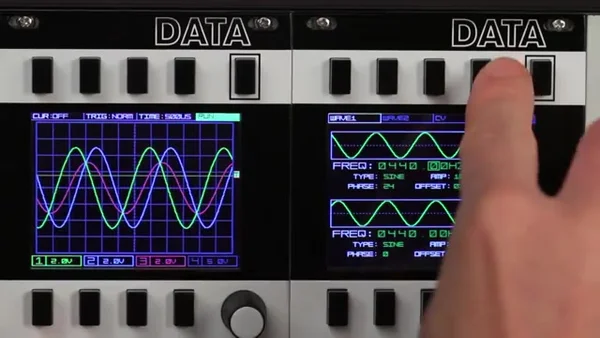
The Waveform Generator program provides two high-precision waveform generators. Each one works as a modulation source like an LFO or as an audio-rate oscillator, and both support 1V/octave CV pitch tracking across eight octaves.
Amplitude and Offset
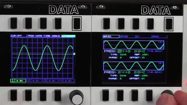
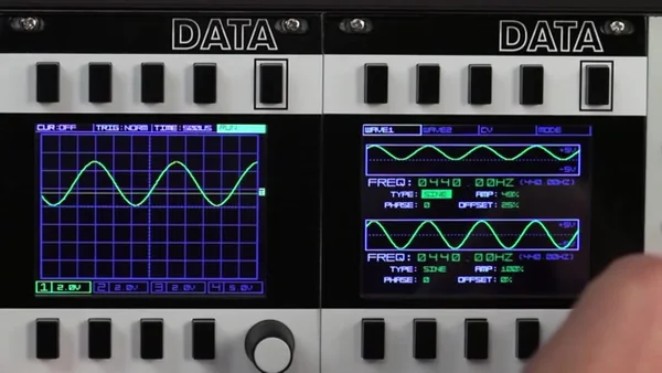
Each generator's waveform can be shaped with AMP (amplitude) and OFFSET (center voltage). In the demo video, a +5V to -5V sine wave is scaled to half its amplitude to make a 5V peak-to-peak waveform, and then the offset is moved to create a 0V to +5V signal centered on 2.5V. That shape is handy when you're using the waveform as a CV source, like an LFO.
Waveform Types
There are four base waveforms to choose from: SINE, SQR (square), SAW, and TRI (triangle).
The AMP control doesn't just attenuate — it can add gain as well, and when you push the gain far enough that the waveform exceeds the ±5V limit, clipping occurs and the shape of the waveform itself changes. In the demo video, gain is applied to a saw wave to turn it into a trapezoid.
Phase and Phase Cancellation
PHASE sets the starting point of the waveform cycle. In the demo video, both generators start at the same frequency and the same phase, with their combined signal shown on channel 3 of the scope. As the phase of oscillator 1 is shifted, the two waveforms separate, and you can watch the amplitude of the combined signal change as the phases cancel each other out.
Frequency and Note Mode
You can set the frequency quickly and precisely by selecting any digit of the displayed frequency value and scrolling it. The TUNE setting under MODE also switches the frequency readout between a decimal frequency and a note value. In note mode, scrolling moves in semitone steps, and both the note name and the frequency are displayed.
The base frequency range is 0.01Hz to 9,999.99Hz when set manually, and 0.01Hz to 4,200.00Hz via CV input.
CV Control and the DVCA
Each generator's frequency and amplitude can be CV controlled from any of the four input jacks. CV control over amplitude effectively works as a digital VCA — a DVCA.
In the demo video, an AD envelope from a Make Noise Maths (CV2) controls oscillator 1's DVCA, while the pitch output of an Audio Damage Sequencer 1 (CV1) controls oscillator 1's frequency. Switching the frequency's CV source over to CV2 puts a single Maths AD envelope in charge of both pitch and amplitude.
Clock Output
The Clock Output program provides CV-controllable clock trigger outputs that either run from the internal master clock or sync to an external clock source. The current firmware supports four outputs. Each output's rate can be set as a division or multiplication of the master clock (DIV/MULT), and you can offset it from the source clock by up to ±96 ticks — one quarter note.
Internal Master and External Sync
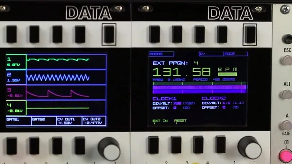
The clock can be generated internally, or synced to an external clock signal with high accuracy. In external sync mode, the pulses per quarter note (PPQN) of the incoming clock signal are shown at the top of the screen. On the current firmware this value is fixed at PPQN = 4 — sixteenth notes. Once DATA locks to the external clock, the BPM appears, with the clock pulse's frequency and period shown below it.
On the demo video's prototype screen, colored bars across the middle show the clock pulses per bar: the top bar is the resolution of the incoming clock, and the others represent the resolution of DATA's own clock outputs, which change according to the DIV/MULT values and the offset. The current firmware's clock screen is built around numeric CLOCK1–CLOCK4 readouts instead, and has no such bars.
DIV/MULT and Offset
DIV/MLT sets the division or multiplication of the base clock frequency. 1:1 gives you quarter notes, x4 gives you sixteenth notes (PPQN 4), and so on. OFFSET shifts the clock output from the base clock by up to ±96 ticks — one quarter note.
In the demo video, a clock externally synced to an Audio Damage Sequencer 1 drives a complex patch. It shows that changing DIV/MULT preserves the relative position of clock 1's sequencer within the bar, that this position is maintained even when the sequencer is started and stopped, and that the offset can shift the beat.
Voltage Monitor
The Voltage Monitor program has a 4-channel voltmeter with a time display, plus four output channels. At the time the demo video was recorded it was introduced as a program still in development, but it's now a proper, shipping feature.
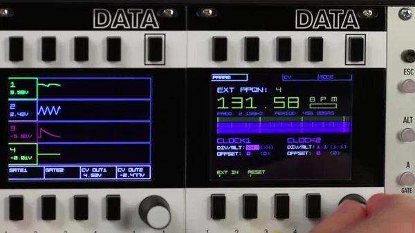
It displays the voltage levels at the four input jacks like a simplified scope, with the current voltage shown numerically in each channel's header. About 12 seconds of input history is visible; the thick dotted center line is 0V, and the two thin dotted lines mark ±5V. This display is designed for monitoring steady or slowly changing signals — LFOs, sequencers, manual CV/Gate control, and the like.
CV / Gate Outputs
The bottom of the screen has the voltage output controls. Each output channel can be set to a constant DC voltage (CV), a momentary Gate (GATE-MO), or a latching Gate (GATE-LA). The output range is -5V to +10V.
In the demo video, pressing the Gate button sends a momentary pulse out of the clock output, and a user-defined CV output voltage is sent from the waveform output. It goes further from there, showing the Voltage Monitor's Gate output switching an effect on the main audio on and off while two CV outputs modulate parameters on another module.
Most DATA programs with outputs reset to 0V when you leave them, but the Voltage Monitor is the exception. CV voltages set in the Voltage Monitor are held even after you move over to the Tuner, Oscilloscope, or the spectrum programs — so you can keep a fixed voltage on the output while measuring something in a different program.
That's it for EP.3. This time we covered DATA's signal-generating programs: the Waveform Generator, Clock Output, and Voltage Monitor. That means we've now been through all of DATA's major programs. From measurement and visualization through to signal generation, DATA's defining trait is that one module lets you see, measure, and create voltage.
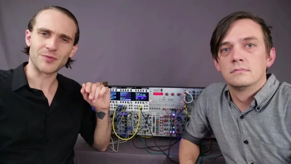
The demo video referenced throughout this article is Mordax Systems' official demo video. Do check the video itself to see the screen in motion and hear how it sounds.
Mordax DATA Product Details
You can find the product details for the Mordax DATA below.
A 16HP multi-purpose utility combining an oscilloscope, spectrum analyzer, tuner, and voltage monitor, plus a 2-voice digital oscillator and clock generator. Helps you debug patches and understand how voltages behave at a glance. Black panel version.
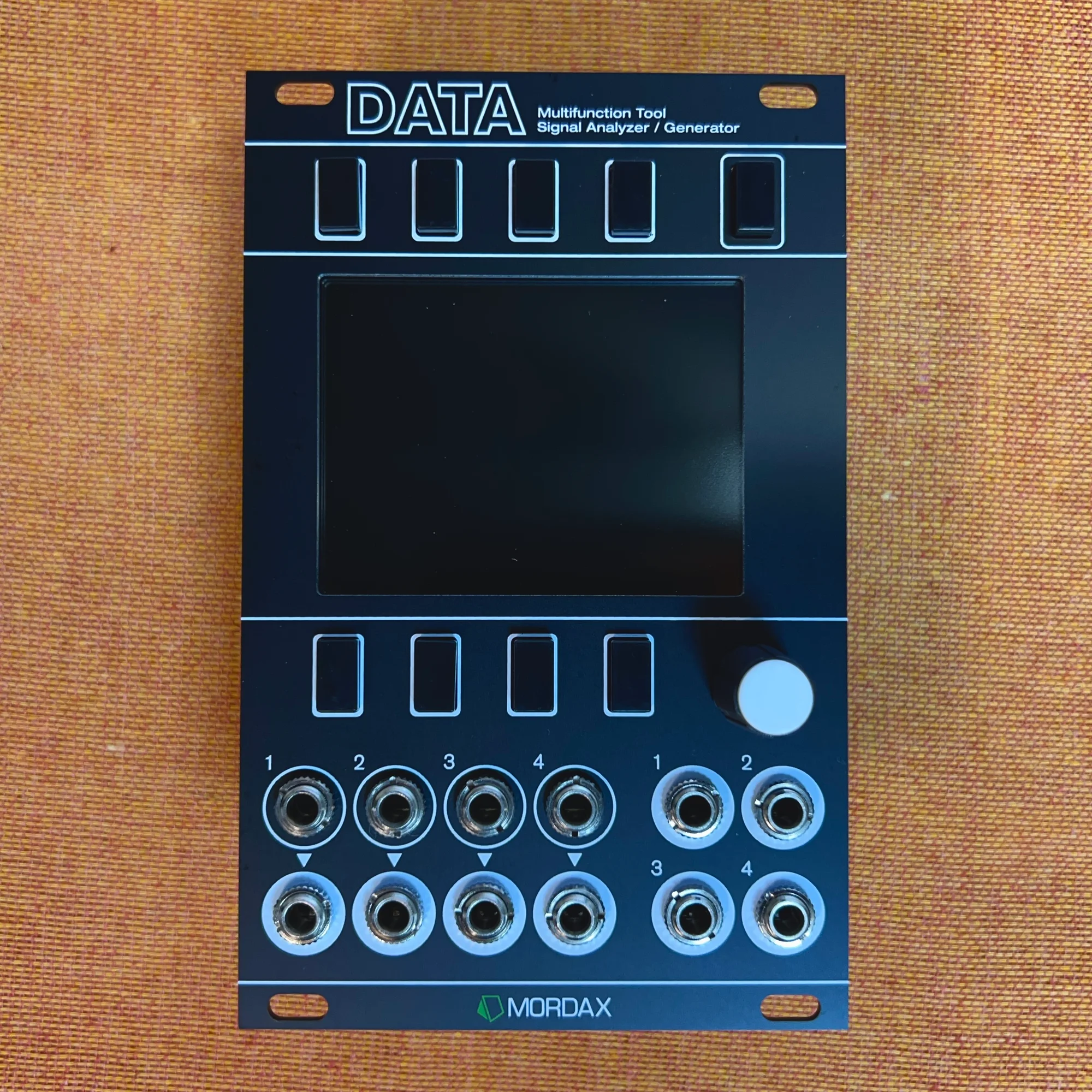
A 16HP multi-purpose utility combining an oscilloscope, spectrum analyzer, tuner, and voltage monitor, plus a 2-voice digital oscillator and clock generator. Helps you debug patches and understand how voltages behave at a glance. Silver panel version.