This is an introduction to the ADDAC216 Sum & Difference by ADDAC System, available at Takazudo Modular.
The ADDAC216 is essentially a two-section mixer. However, this two-section mixer is capable of diverse CV/audio synthesis processing. Each section has two CV input jacks, offering individual Attenuvert, signal mixing, Full Wave Rectification, AC coupling, signal inversion, and average calculation -- all in a single module.
This product is available for purchase below.
Takazudo Modular publishes manuals and related documents with Japanese translations. See the links below.
- Product Photos
- ADDAC216 Overview
- ADDAC216 Explained
- When to Use the ADDAC216
- Technical Specifications
- Included Accessories
- Manual
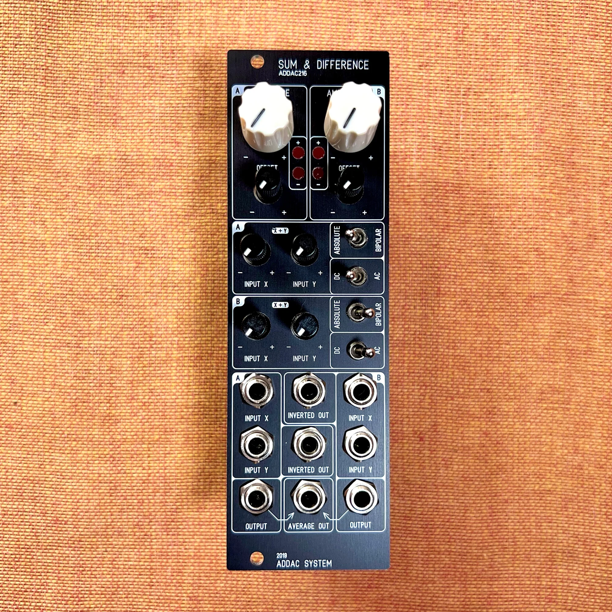
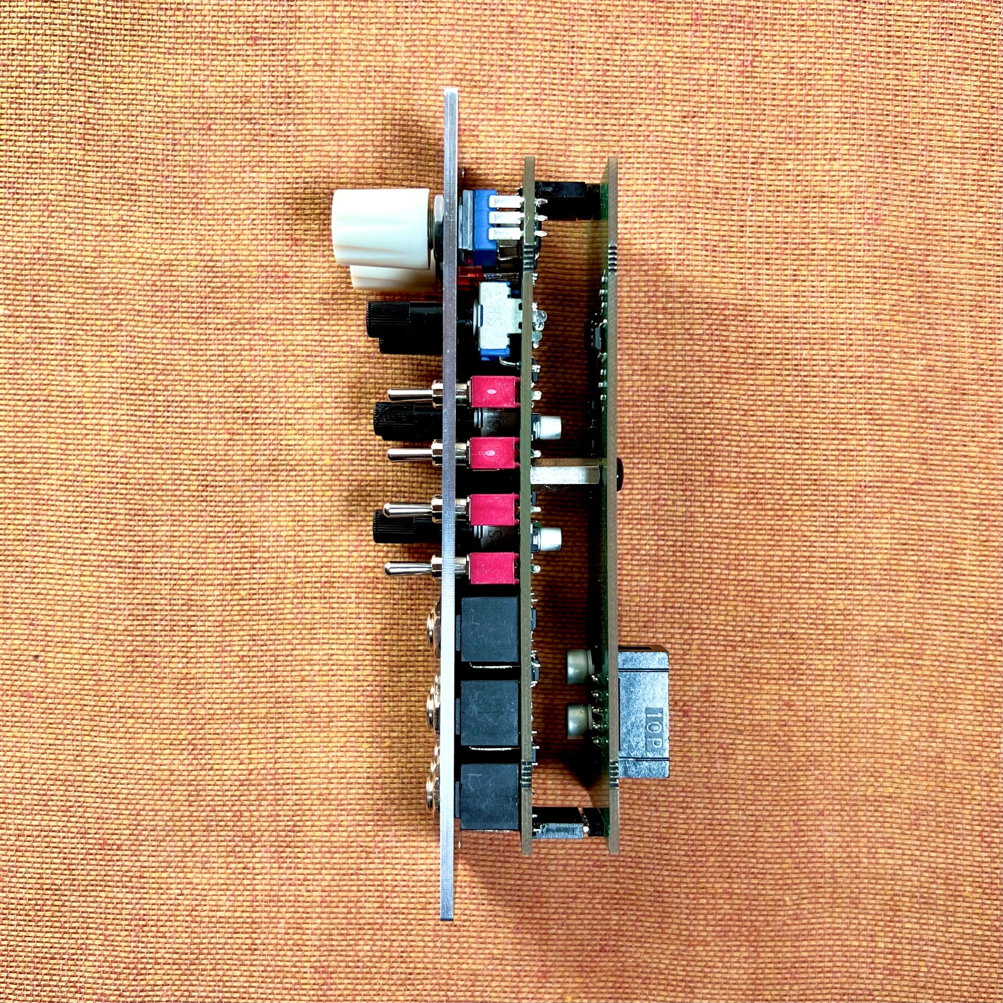
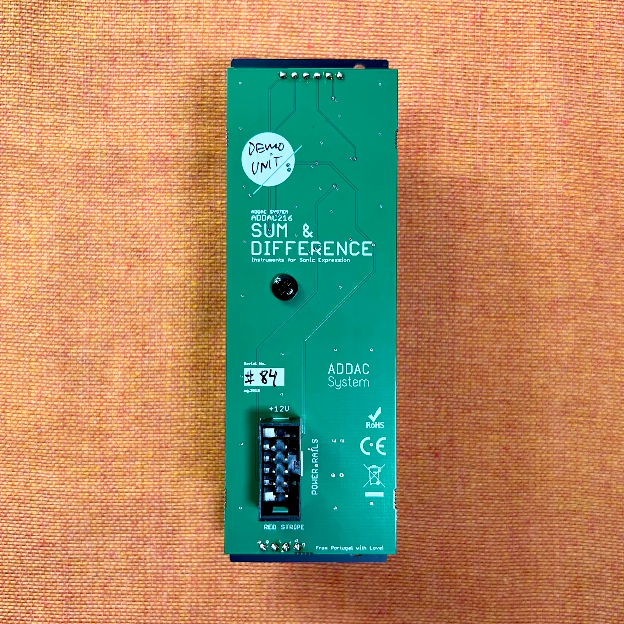
Product Photos
ADDAC216 Overview
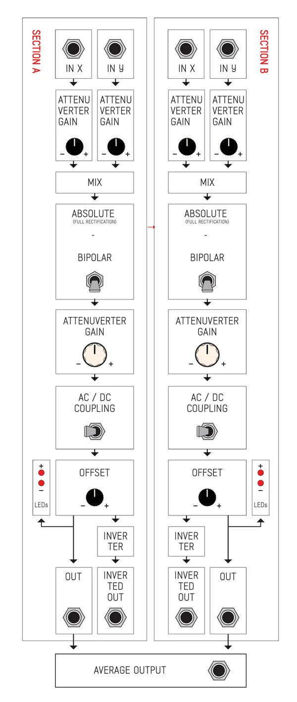
To understand what this module does, it helps to look at the signal flow diagram (quoted from the manual).
This module consists of two identically functioning sections labeled A and B. The two sections are independent -- think of it as two sets of CV addition/subtraction processing blocks.
This module is fundamentally a mixer, but unlike a standard mixer that simply adds two input signals (from IN X and IN Y), it is a special type of mixer that can also subtract signals.
Furthermore, it handles both audio signals and CV signals, allowing you to output the difference between two CVs or cancel the phase of two audio signals.
The signal resulting from addition or subtraction then passes through a switchable (on/off) Full Wave Rectification circuit labeled ABSOLUTE.
After that, the mixed signal's gain passes through another Attenuverter labeled AMPLITUDE, which controls the resulting signal gain. Following the Amplitude stage, there is an AC/DC coupling switch, followed by a bipolar offset knob.
In addition to the standard output, each section (A and B) also has an inverted output (INVERTED OUT). The outputs of sections A and B are summed and sent to the AVERAGE OUT.
When using only a single input (X or Y input alone), this module can also function as a simple dual attenuverter and offset CV processor, with Full Rectification and AC coupling available.
ADDAC216 Explained
Fully understanding everything this module does can be quite challenging for someone just getting started with modular synthesis. For such users, it may be easiest to think of this as a module that lets you add, subtract, and otherwise manipulate CVs in many different ways all at once. Conversely, when you find yourself wanting to do that kind of CV synthesis processing, having this single module covers a wide range of possibilities.
In this section, I will briefly explain what the addition and subtraction mentioned so far actually mean in practice. To understand what the ADDAC216 can do, it may be quicker to first understand what simpler modules do. The following module introductions also cover CV addition, subtraction, and Attenuvert, so please check them out as well.
Additionally, for this kind of CV synthesis processing, while you can eventually learn to visualize it mentally, as a learning step I recommend using an oscilloscope such as Mordax: DATA or Korg: NTS-2 to see and understand what is happening.
With that said, let us go through each concept one by one.
Addition
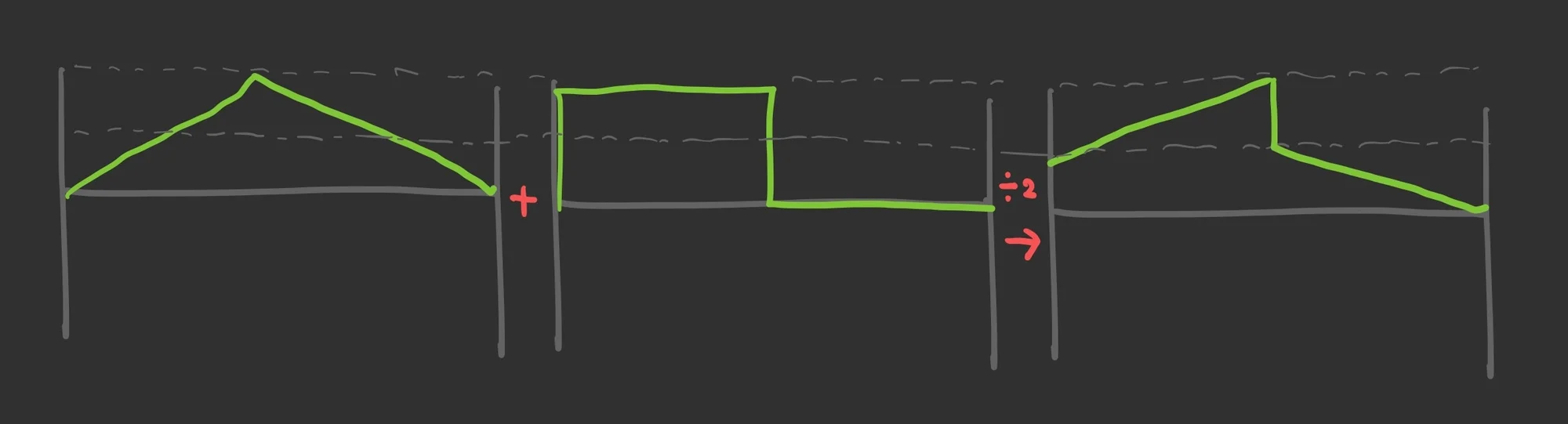
First, as with any mixer, mixing two voltages means adding them together. Below is a diagram showing an example of adding two voltages.
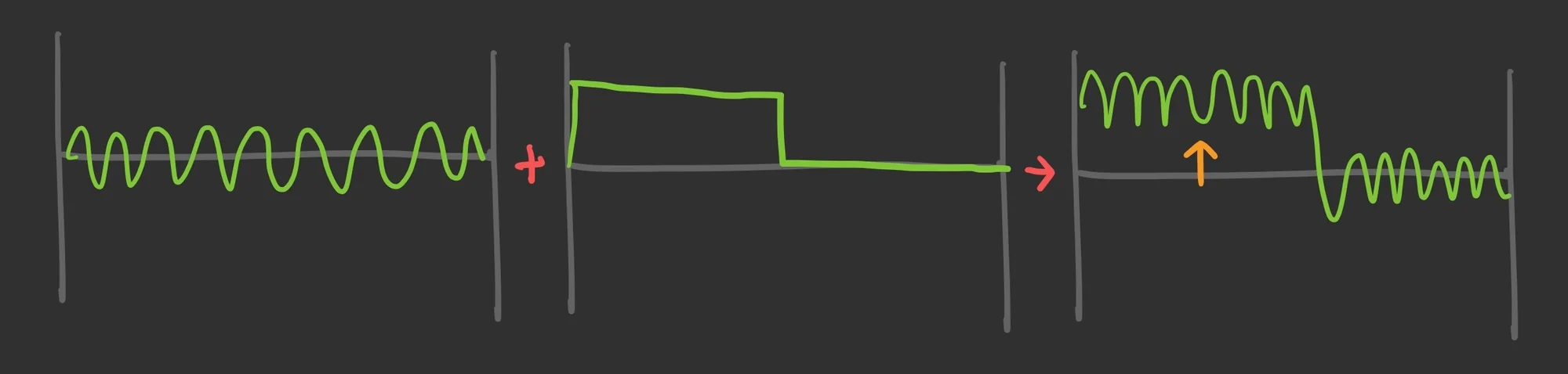
The first waveform is a sine wave. The second waveform shows a positive voltage in the first half, followed by 0V (no voltage applied) in the second half.
Since only the first half of the second waveform is positive, the result of adding the two voltages is that the first waveform shifts upward in the first half by the amount of the second waveform's positive voltage.
A waveform represents voltage on the vertical axis and the passage of time on the horizontal axis, which can make it somewhat tricky to visualize. Imagine that at every point along the horizontal time axis, the two voltages at that moment are being added together.
Subtraction
Regarding subtraction, on this ADDAC216 it works by inverting a signal to negative using the Attenuverter and then adding it. If we take the same example from the previous section and subtract instead, the diagram looks like this:
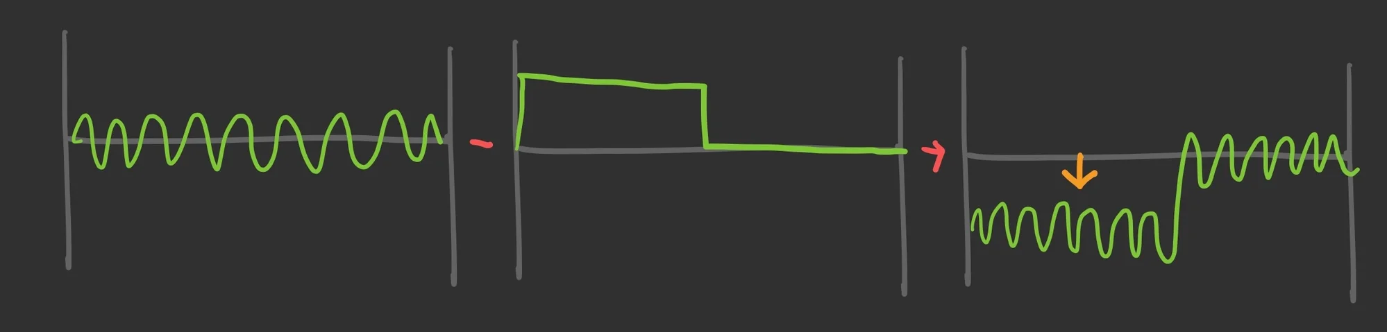
Here, the portion that was lifted upward in the first half is now pushed downward instead, resulting in a negative voltage. It is essentially flipping the signal and then adding.
Full Wave Rectification
I mentioned earlier that Full Wave Rectification processing is available. This is the processing that occurs when the switch labeled ABSOLUTE / BIPOLAR is set to BIPOLAR. When this switch is set to BIPOLAR, the incoming voltage passes through a Full Wave Rectification circuit, and the result is that the voltage is converted to its absolute value.
While it sounds complicated in words, what happens is that negative voltages are multiplied by -1 and converted to positive voltages. The diagram below illustrates this.
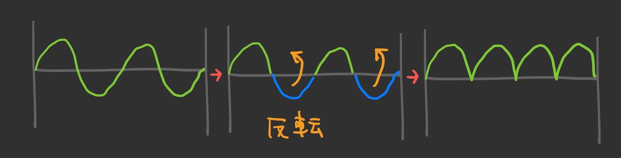
This type of processing is called Full Wave Rectification.
AC Coupling
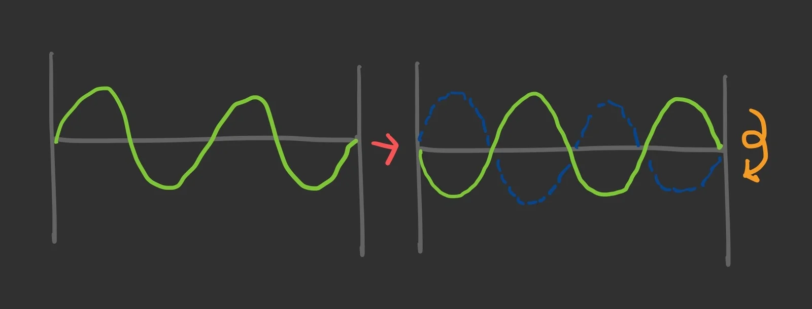
Switching the DC / AC toggle to AC enables AC coupling. This is a process that adjusts a voltage that has shifted up or down (a state called having a DC offset) so that its center value returns to 0V. The diagram below shows the waveform before processing on the left and after AC coupling on the right.
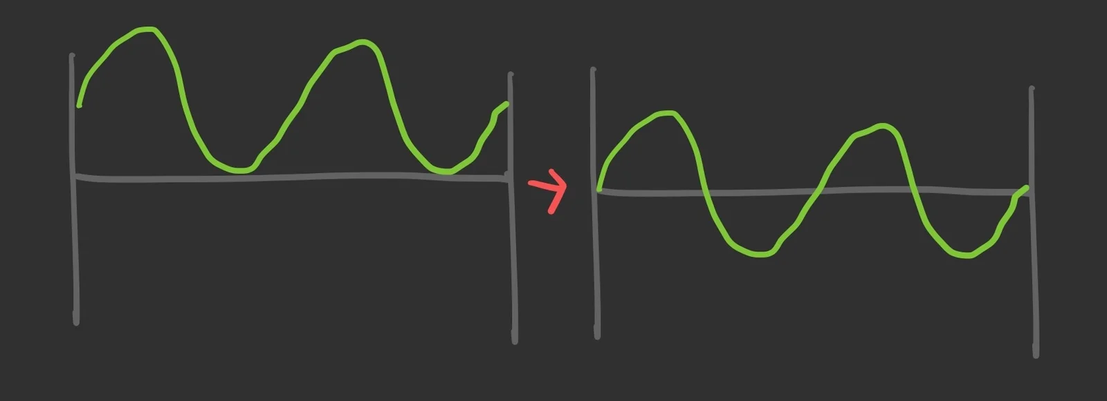
When using a modular synthesizer, you freely shift voltages up and down and use them as signals to modulate parameters. However, when it comes time to send the final signal to a speaker to produce sound, you almost never use a waveform whose center value is not 0V, as shown in the original waveform above.
Generally, audio processing equipment corrects such voltage offset (DC offset) before passing the signal to speakers. AC coupling is used for this purpose, and performing AC coupling can help prevent speaker damage and improve sound quality.
By switching the DC / AC toggle on this ADDAC216 to AC, you can apply this processing. In short, this function is useful when you are processing a voltage as audio and the result has an unwanted upward or downward voltage offset, which could cause various issues.
Noise Cancelling
As the author Takazudo, I have very little experience doing detailed audio signal processing with a modular system, so my knowledge here comes from research done while writing this article. For example, noise cancelling technology is, in simple terms, a technique that subtracts the external ambient sound signal from noise-contaminated audio.
While similar things can likely be done with this ADDAC216, when you want to use the output from this module as an audio signal after processing audio in some way, you might use AC coupling to eliminate a problematic DC offset in the center value of the voltage. (Reference: YouTube: Super easy-to-understand explanation of audio phase - flstudio)
Inverted Output
The INVERTED OUT jack at the end of the ADDAC216 outputs the voltage inverted -- that is, the result of multiplying by -1.
Average Output
The AVERAGE OUT at the very end outputs the average voltage -- the sum of the voltages produced by the two sections, divided by two.
The term "average" might sound complicated, but when you keep adding voltages together -- for example, summing multiple LFOs -- you can easily exceed the typical +5V to -5V range commonly used in modular synthesizers. In such cases, the average voltage from this bonus AVERAGE OUT can be quite useful.
When to Use the ADDAC216
That covers what this module can do. The author Takazudo considers this module to be a strong contender whenever you need a CV mixer. Whether you want to manipulate CVs in various ways depends on the individual, but personally, I frequently add and subtract CVs from sequencers.
When you want to add, subtract, and invert CVs like this, you can end up needing multiple modules for such small tasks. For example, if you want to shift an LFO slightly into the negative range and add it to a CV output from a sequencer, you would typically need a separate Attenuverter in addition to a standard mixer.
In such situations, this module serves as a versatile all-in-one utility CV mixer. In my personal experience, having two sections that each mix two CVs is just the right amount.
Full Wave Rectification might prompt a "what would I use that for?" reaction based on the explanation alone. However, processing oscillator waveforms or running modulation LFOs through it can lead to sound design results you would never arrive at through straightforward patching -- and that, in my opinion, is one of the joys of modular synthesis.
I encourage you to try this module when experimenting with CV manipulation.
Technical Specifications
Width: 8HP
Depth: 36mm
Power consumption: 80mA +12V / 80mA -12V
Included Accessories
Power ribbon cable
Screws
Manual
The manual is available on the official website below.
About ADDAC System
ADDAC System is a modular synthesizer maker based in Portugal.
Their lineup is built on solid, no-nonsense modules that make the most of analog character. At the same time, they have released plenty of inventive modules that bring digital technology into the mix in a tasteful way — flexible CV-to-MIDI converters, deeply controllable granular processors, and more.
Bonus: Modular Accessory Set by 電氣美術研究會 (Denki Bijutsu Kenkyukai) Included

In the hope that more people will get hands-on with modular synths, we have teamed up with 電氣美術研究會 to bundle a modular accessory set with this product.
The contents vary by season — patch cables, power cables, a dress-nut sample set, a mono splitter, and more. The set is included with the product, so please give it a try!
That concludes the introduction to the ADDAC216 Sum & Difference.
Takazudo Modular publishes manuals and related documents with Japanese translations. See the links below.
We hope you found this helpful.